Getting Rid of Dead Batteries
Published 2026-06-04
Edited 2026-06-06
So, I got a new toll tag. It started with an email that my current one was old technology that was being retired. They wanted to confirm my address to ship a new one. This of course meant an opportunity to take them apart and compare them.
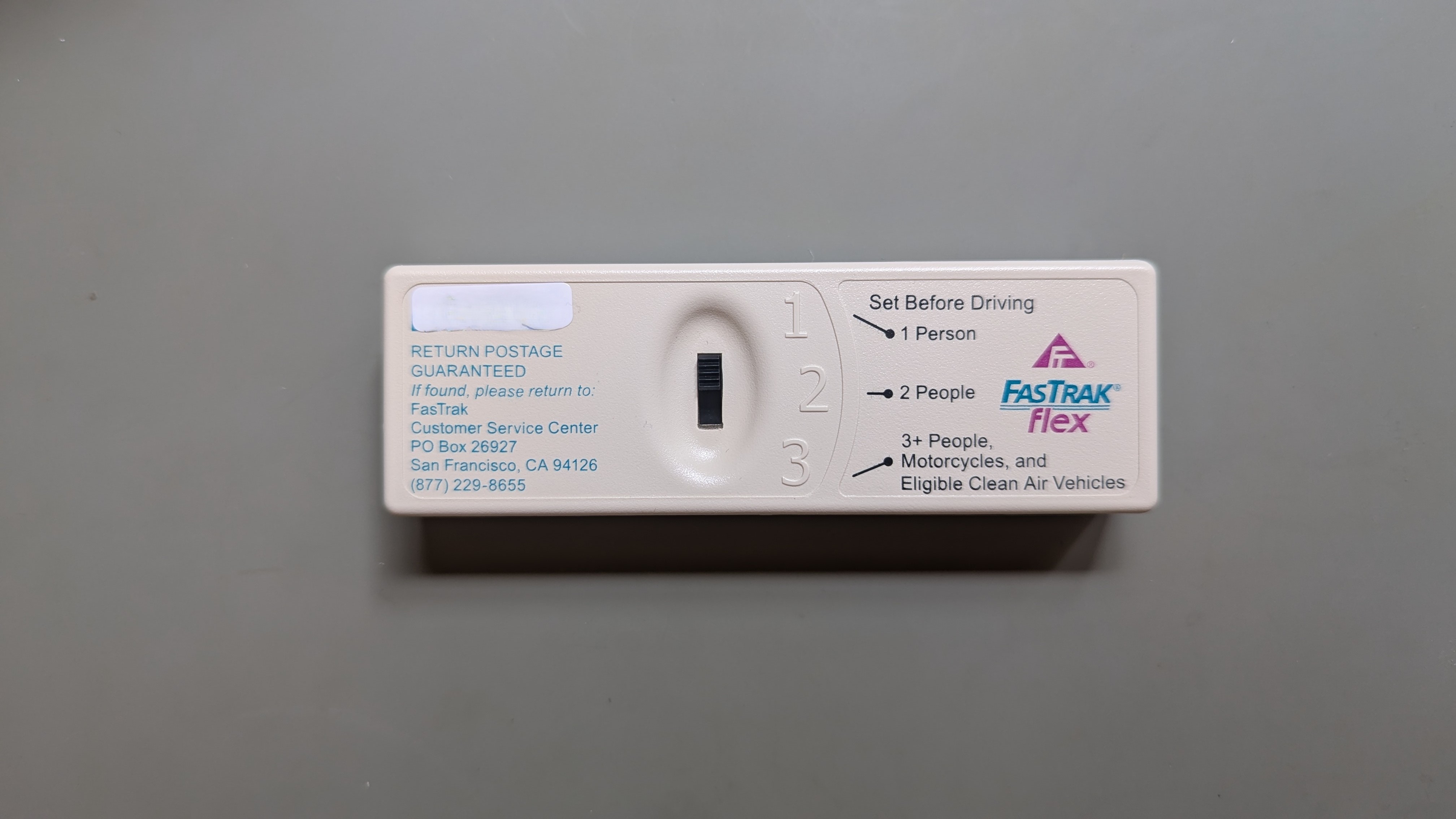

Both have a switch to transmit the number of people in the car for carpools, the old one beeps a number of times to match what it’s set to, both when it’s changed and when going through a toll booth. The new one offers no feedback.
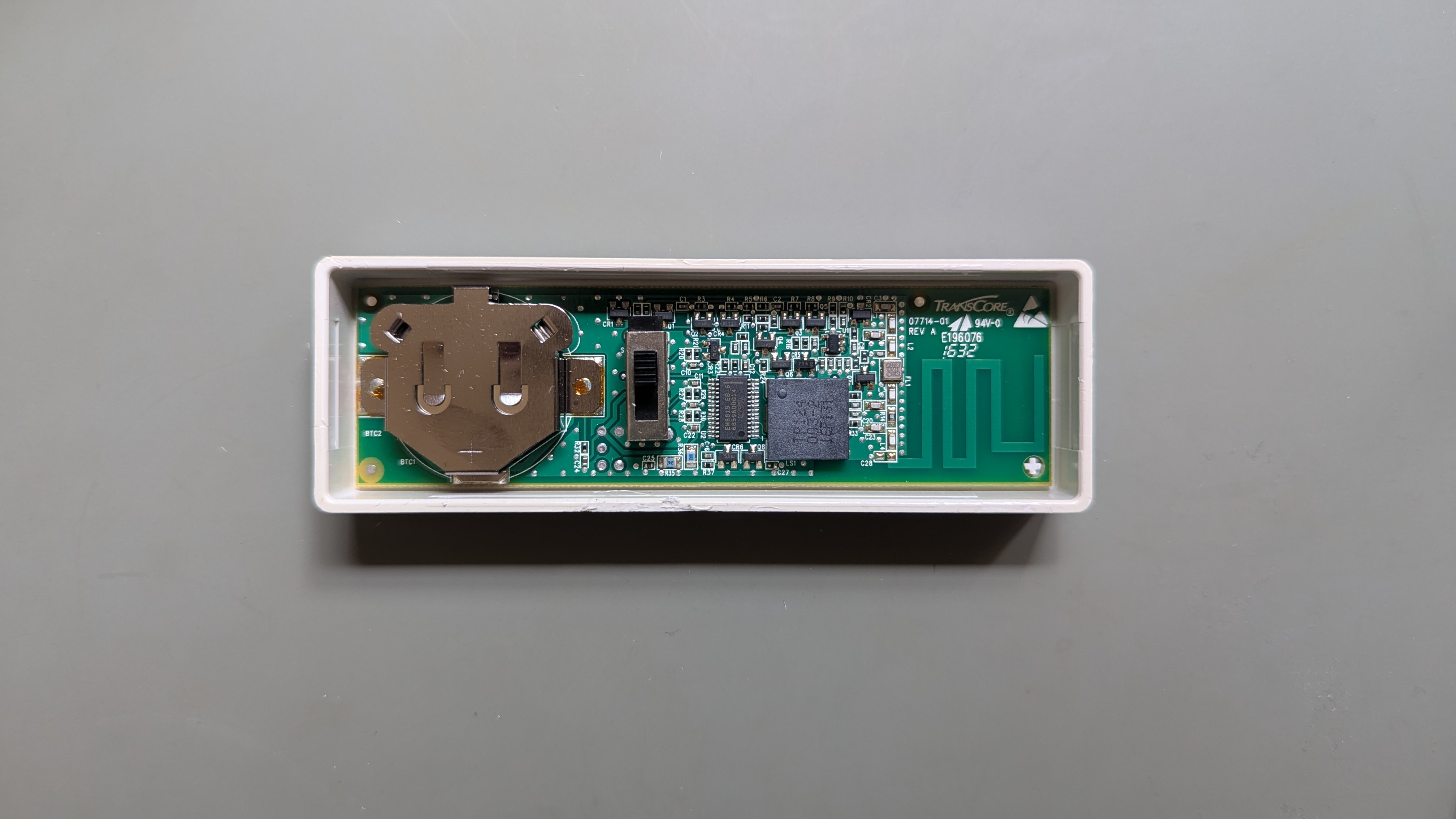
The old one’s housing was just clipped together, and pried open with average effort. I don’t think there is much I can do with the transmitter, so I didn’t put any effort into reverse engineering it. However, it has a heat resistant 3V lithium battery. Unloaded it was about 2.75 V. If the discharge curve is like a typical coin cell, that’s close to dead. I wonder if these models are really obsolete, or if it alerted them that the battery was dying and they don’t want to replace them every 10 years anymore.
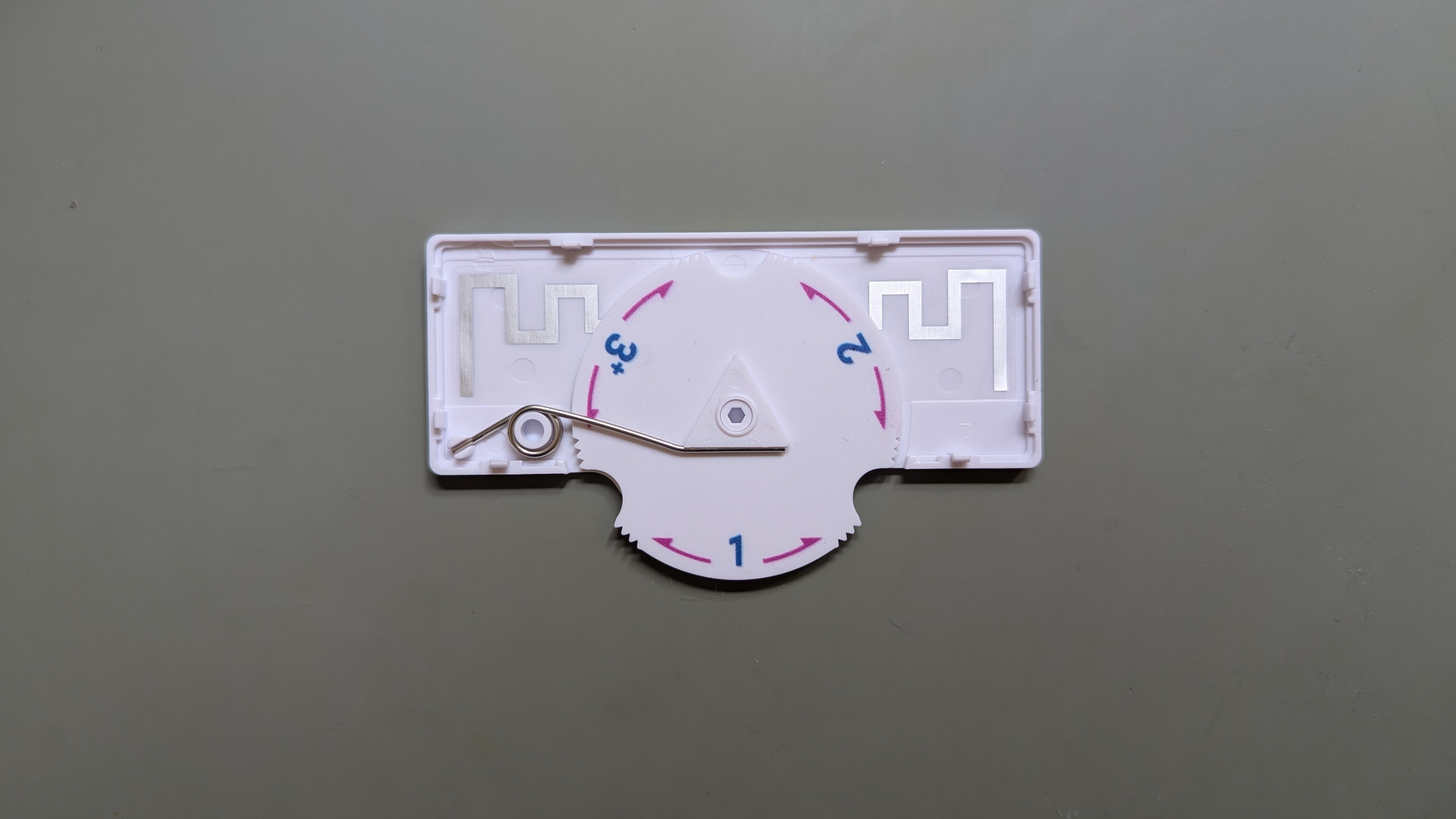
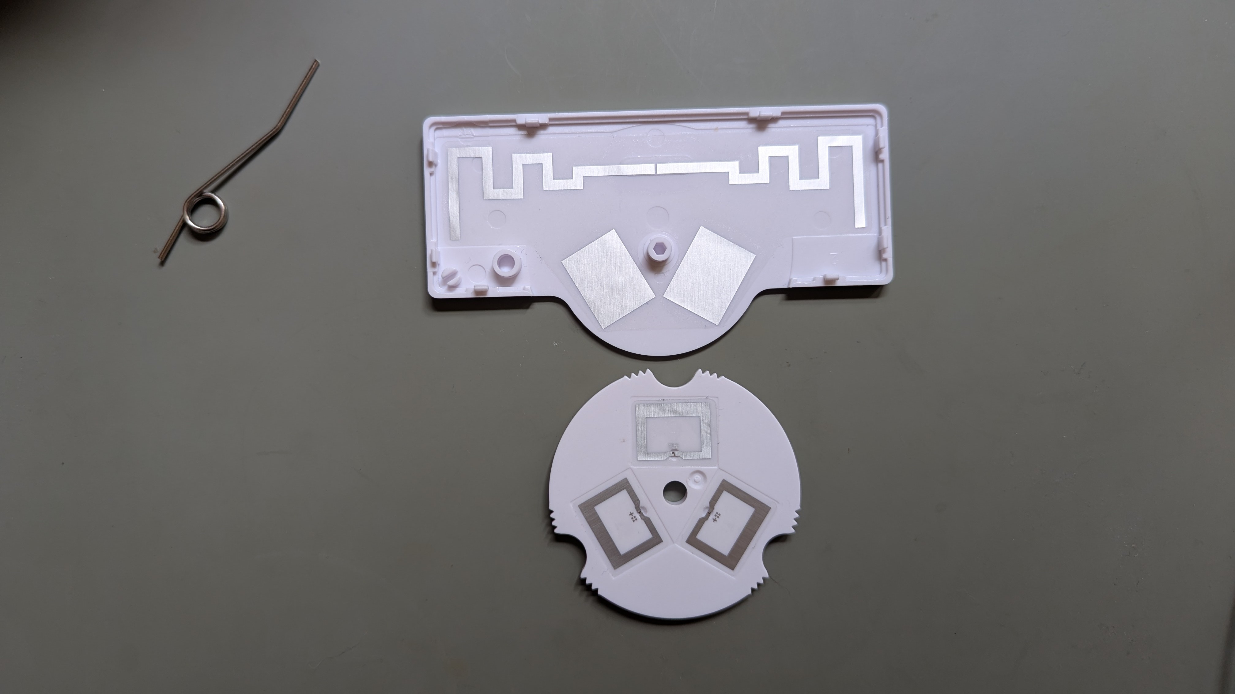
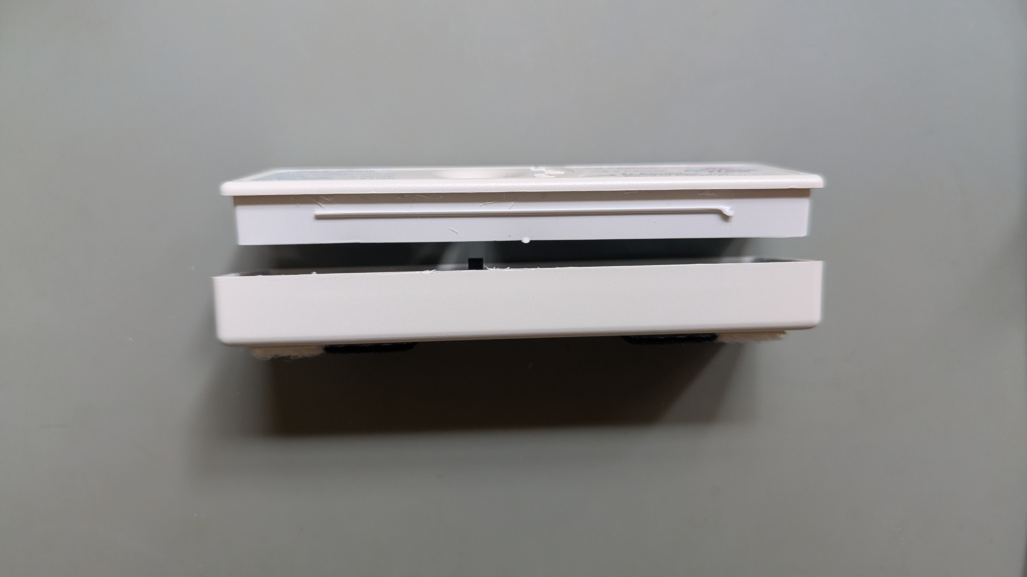
The new one is much flimsier. The housing can be pried apart by hand. Inside is just a spring holding the dial in one of 3 positions. On the back are 3 RFID chips. Two are covered by a metal shield, and one gets coupled to some antenna wings.
I keep the tag behind the rear view mirror, so while driving I can’t even see there’s anything on the windshield. That’s why it’s kind of annoying that the new one can’t offer any feedback on its position without looking. The old one warns not to change settings while driving, the new one does not and it’s the more dangerous design!


My initial idea was to leave position 1 smooth, put 2 notches on position 2, and a flat on position 3. Filing number 3, I noticed that the file put ridges like the edge of a coin, so I ended up doing that over the whole edge. The notches on position 2 were harder than I expected to differentiate from the ridges, so I ended up making them much bigger. Overall I’m happy with position feedback that I can feel without looking, and I think it should have been designed like this from the start!
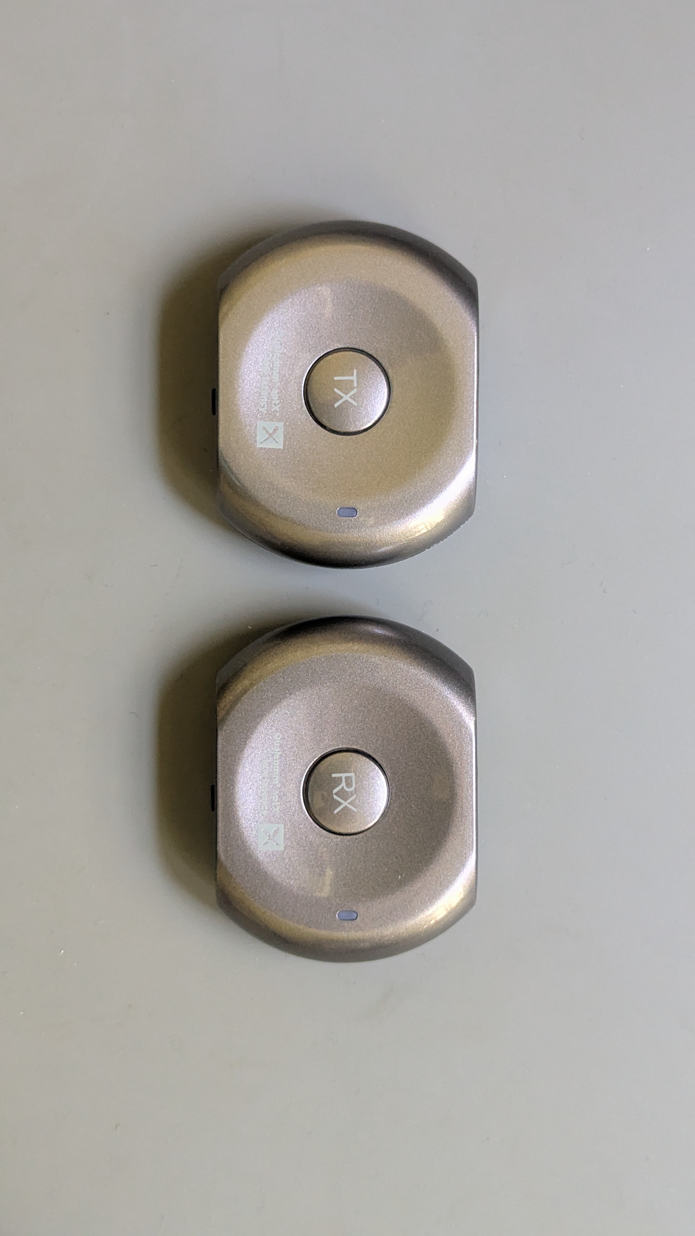
Another project this week was checking on a bluetooth transmitter/receiver pair. I have a projector and its only audio output is a 3.5 mm jack. That means running a cable to the front of the room or having the sound come from behind you. I bought a low latency transmitter and receiver maybe 10 years ago, but ended up with a separate sound system so I rarely used them. Now I’m thinking of using them again.
The issue is that they have batteries even though I would use them permanently plugged in. I don’t really trust the old batteries and don’t want to leave them fully charged and ready to ignite.
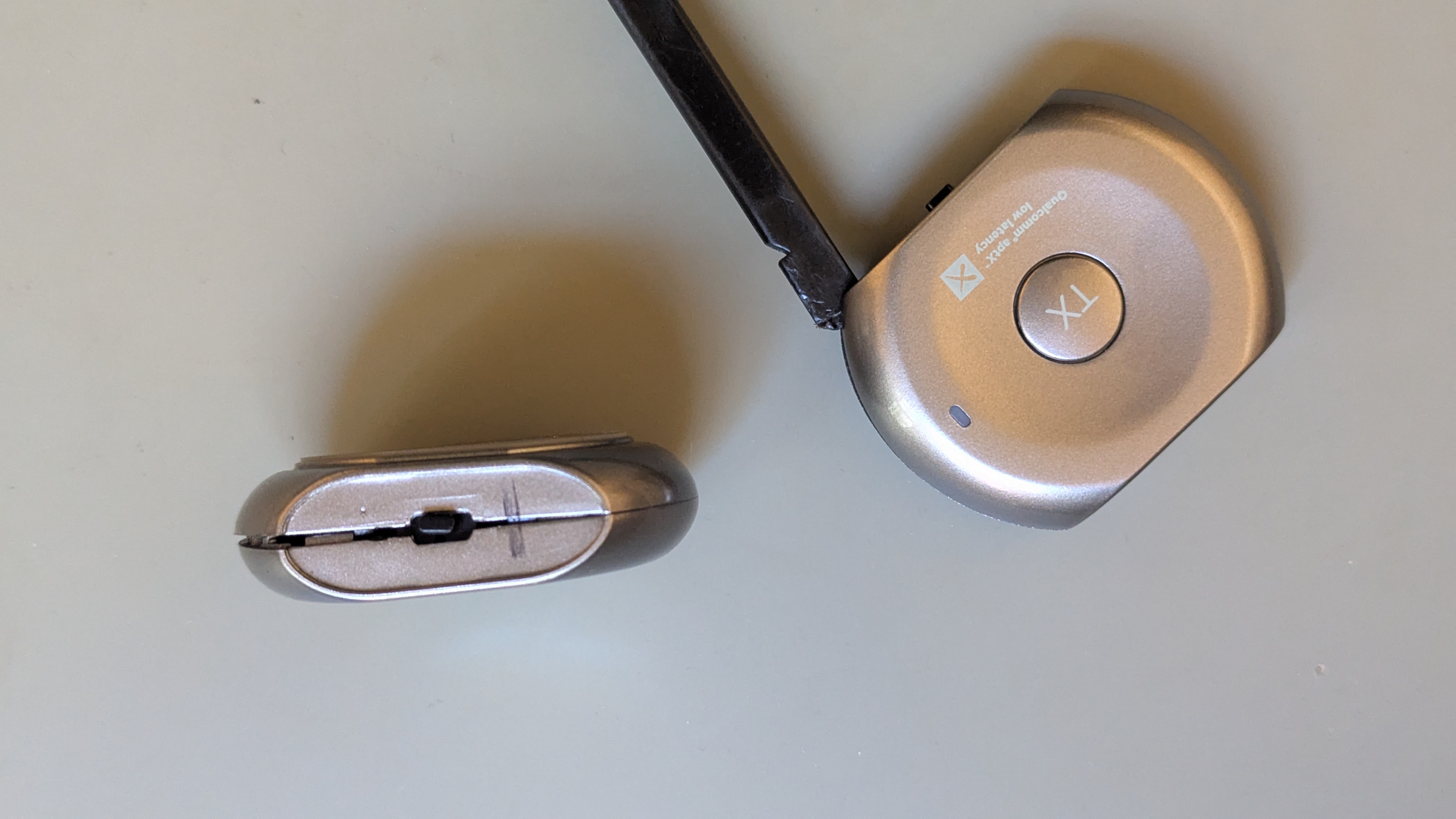
They had stickers over the front and back, but after peeling those off the housing halves unclipped pretty easily.
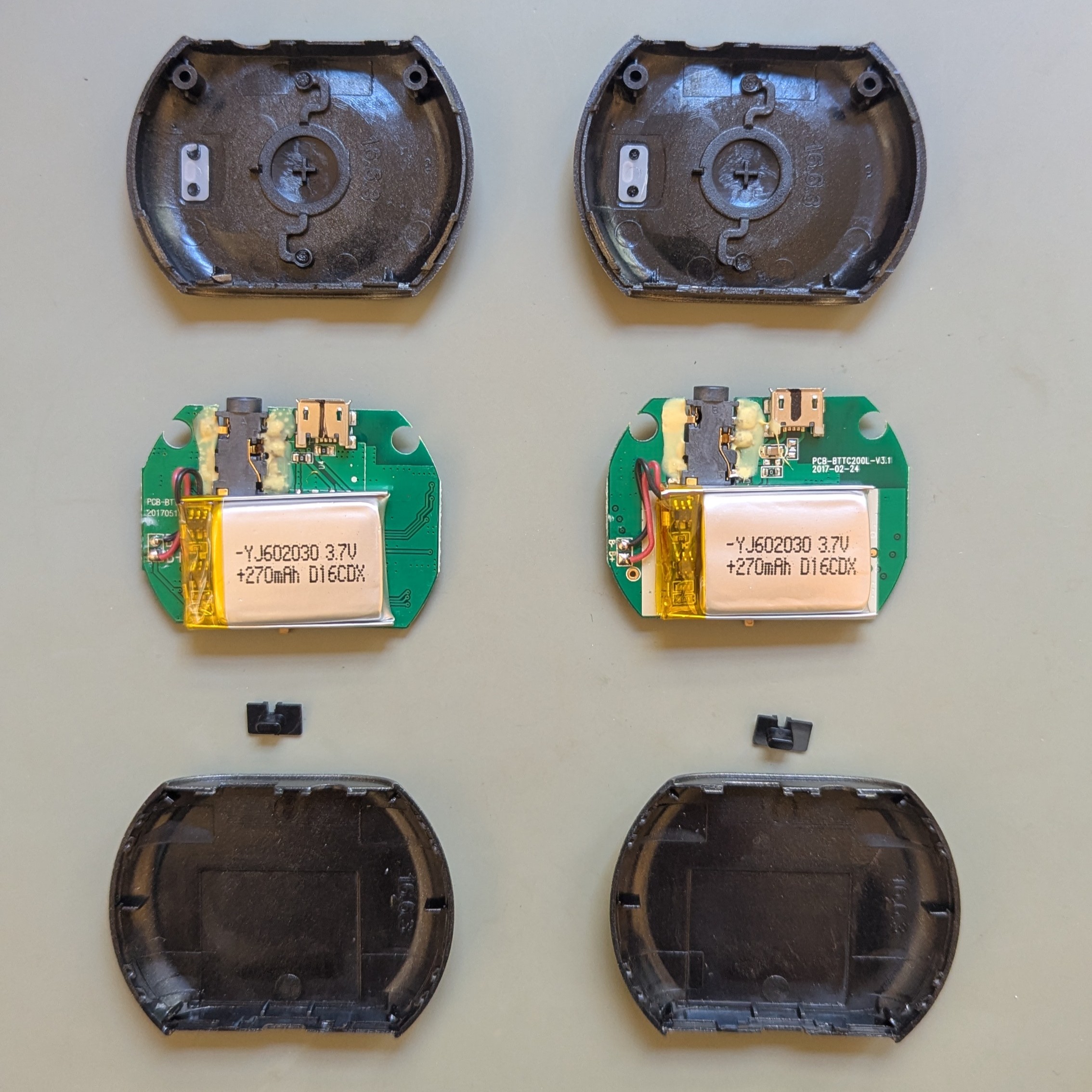
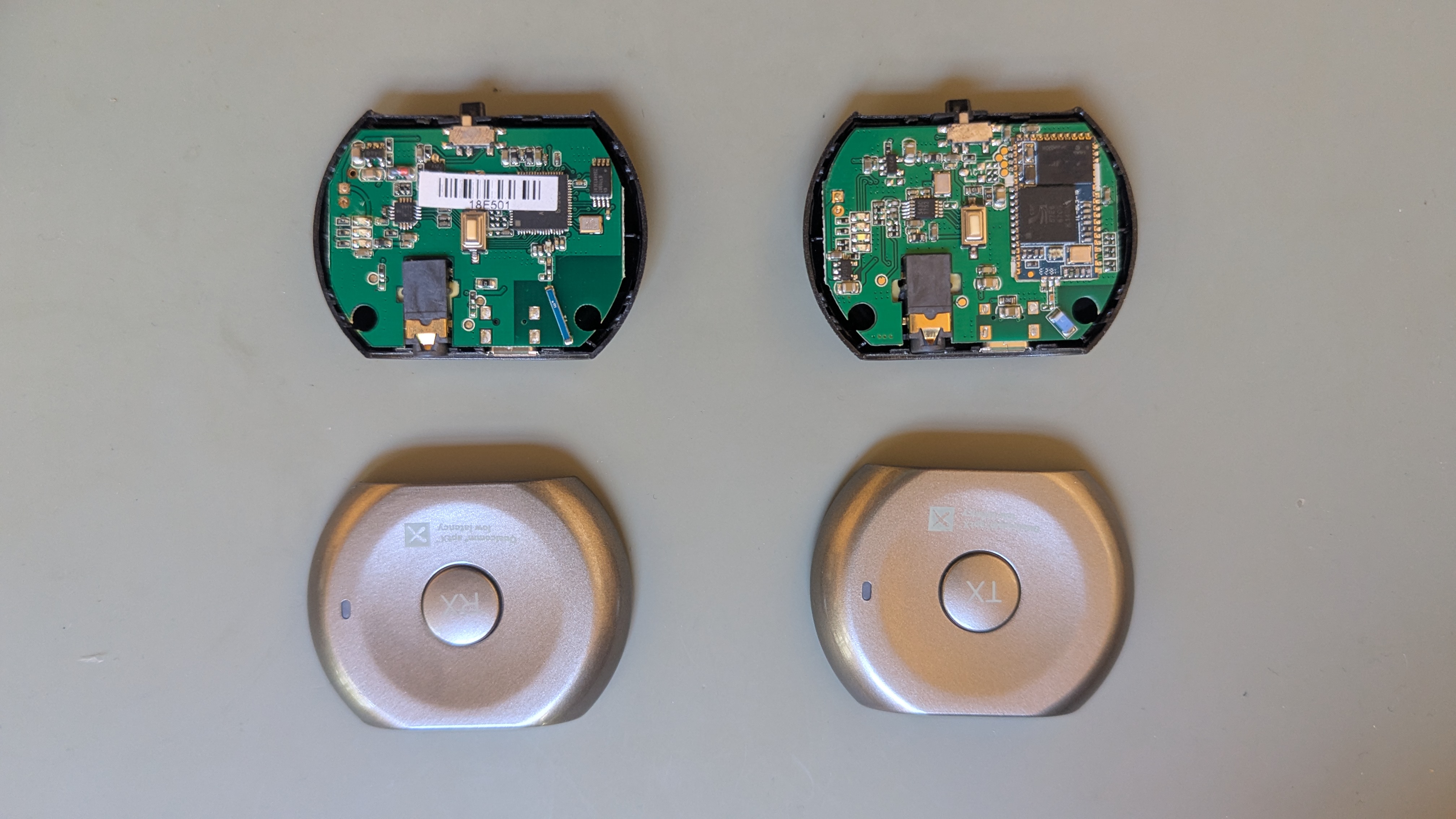
Luckily (for me, but maybe not for safety) the batteries just have a positive and negative terminal going to the electronics. There is some circuitry on the battery that probably handles over and under voltage cut-off, but it means that the bluetooth transmitter part isn’t managing the battery.
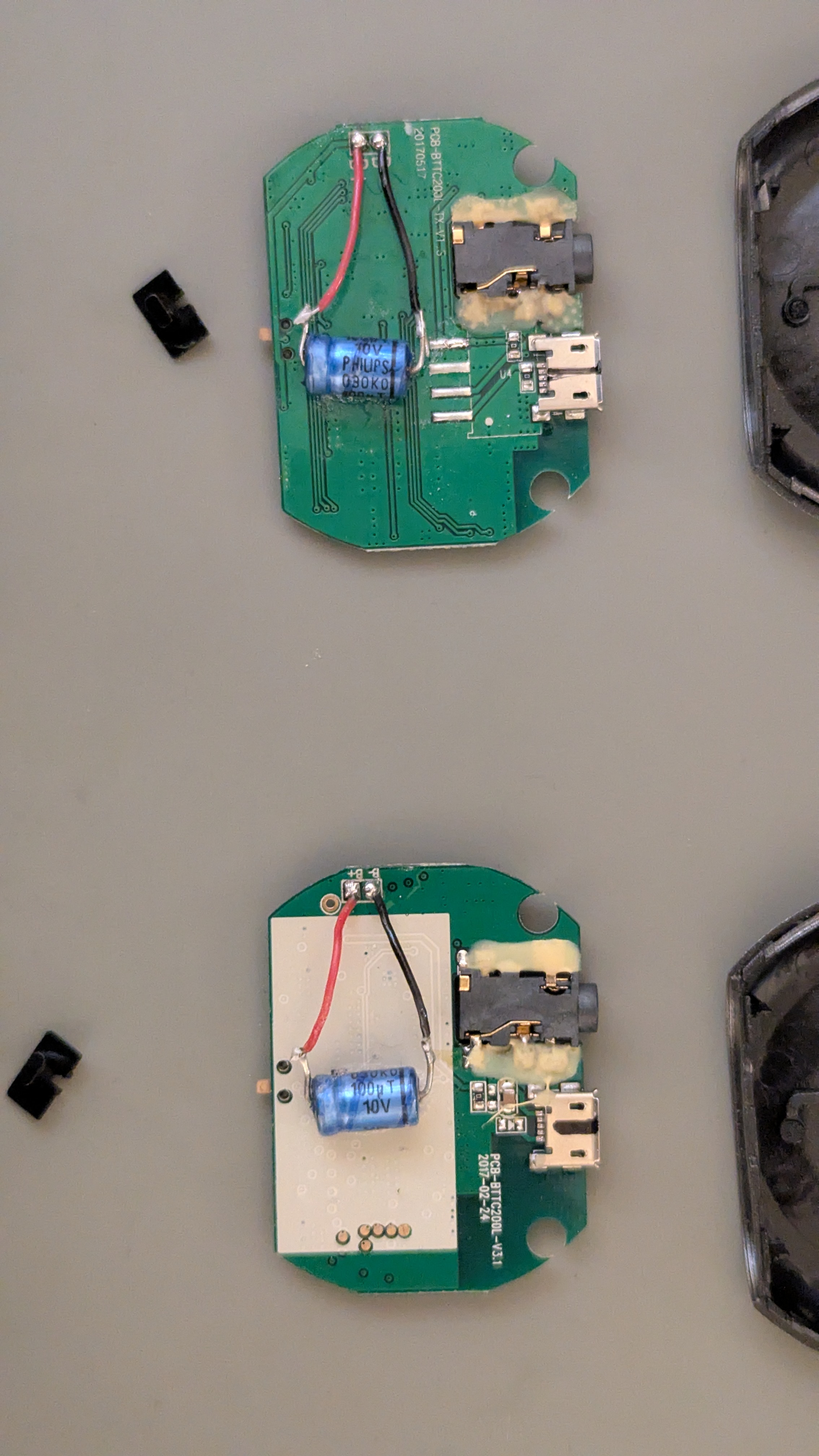
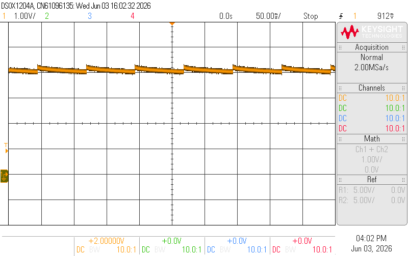
The biggest capacitors I had that were the thickness of the battery were only 100 µF. I soldered them on the old battery leads and checked how they behaved on the oscilloscope.
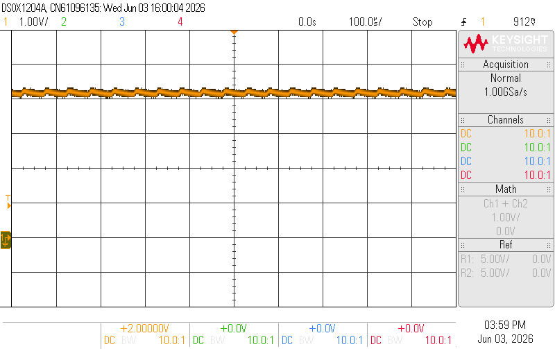
On the transmitter, the ripple is right around 20 kHz, both powered off and powered on. Not ideal, but I probably won’t hear it. Also, if it’s “charging” from 4.1 to 4.2 V, it would be repeatedly draining and charging the battery from 95-100%, so I’m glad I took the battery out. I’ll be able to tell if the ADC picks up any noise from what it transmits.
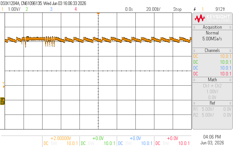
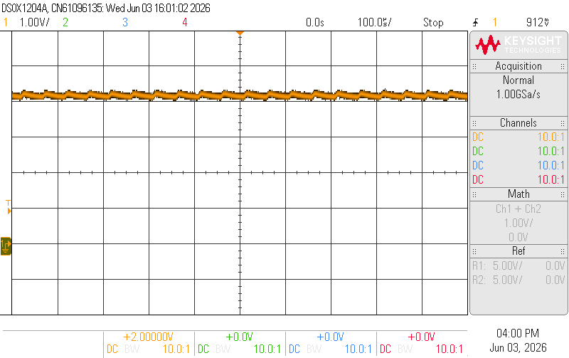
The receiver is not so nice. Powered off it has a much lower power draw and frequency, but turned on it is in an audible range and varies, probably with changing power states in the receiver. Some of those are around 500 Hz, which could definitely be noticeable.
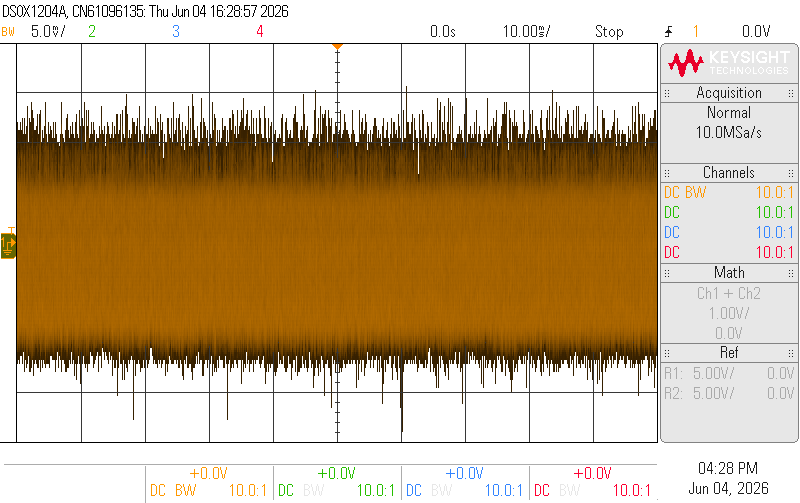
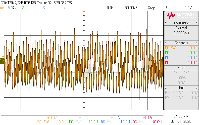
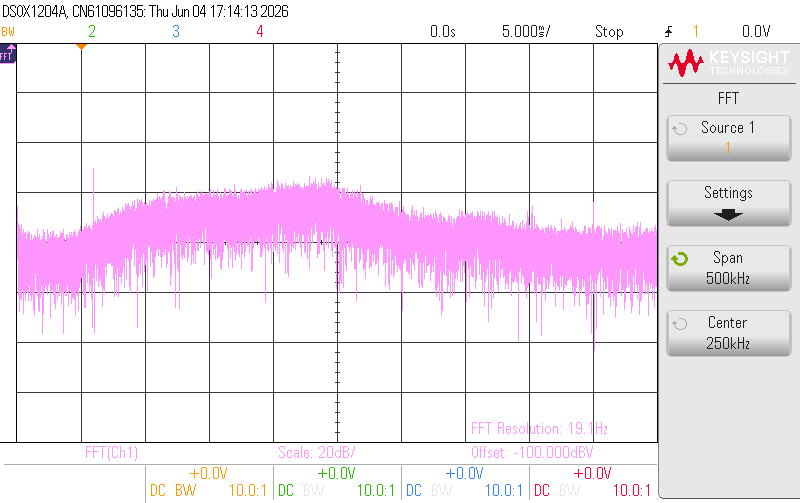
The noise from the output looks terrible, about 20 mV peak to peak, but zoomed in or on an FFT the noise is all well over 30 kHz, and mostly 100 - 250 kHz. Luckily it seems like the power supply noise from either doesn’t get transferred to the audio output.